

How to Style Brick and Timber in Exterior House Rendering
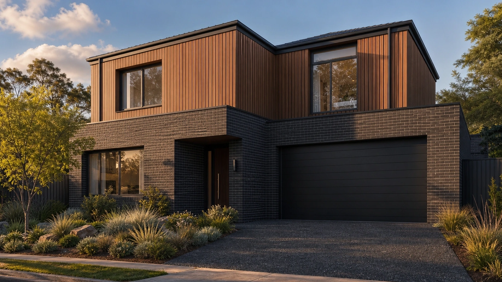
Why Exterior House Rendering with Brick and Timber Fails
The Three Most Common Errors
Scale, map type, and lighting sequence account for the majority of exterior house rendering failures on brick-and-timber facades. They are fixable at the setup stage, not in post-production.
Scale wrong: Standard UK metric brick face is 65mm high and 215mm long. Mortar joint is 10mm. One brick course is 75mm total height. When texture tiling is set at the wrong scale, bricks render at 150mm or 200mm high. The result looks like toy blocks or oversized cinderblocks, and the viewer registers it without being able to name why.
Bump instead of displacement: A bump map is a 2D illusion. When the camera is perpendicular to the wall, it reads plausibly. Rotate the camera to 30 to 45 degrees from the wall, and the mortar joints flatten to nothing because there is no geometry to catch a shadow. An exterior house rendering with the camera at street level, looking at a facade from an angle, exposes every bump-map mortar line as fake within the first second of viewing.
Lighting after materials: Configure materials against a flat, low-resolution HDRI and they will look wrong regardless of how accurate the PBR values are. The correct sequence is: establish lighting, verify it in silhouette, then open the material editor.
Getting Brick Right in Exterior House Rendering
Real-World Scale for UV Mapping
The UV mapping step is where texture scale is set, and getting it wrong is the most common source of unreal-looking brick. The numbers to work from: UK standard brick face is 65mm high and 215mm long. Mortar joint is 10mm. That makes one course 75mm tall.
In 3ds Max, apply a UVW Map modifier to the wall geometry and enable “Real World Map Size.” Set the tile dimensions to match the physical size of the texture you are using. A 3-metre-high wall needs 40 brick courses (3,000mm divided by 75mm). That proportion check confirms the UV scale is correct before a single render runs.
Without this, the same wall section will show visible tiling patches at any render resolution. Adding a UV randomizer node (the Multi-Texture map in V-Ray, or a hash-based offset in Blender) distributes texture rotation and colour variation across individual bricks, breaking up any repeat pattern on facades wider than 2 to 3 metres.
The PBR Map Stack for Brick
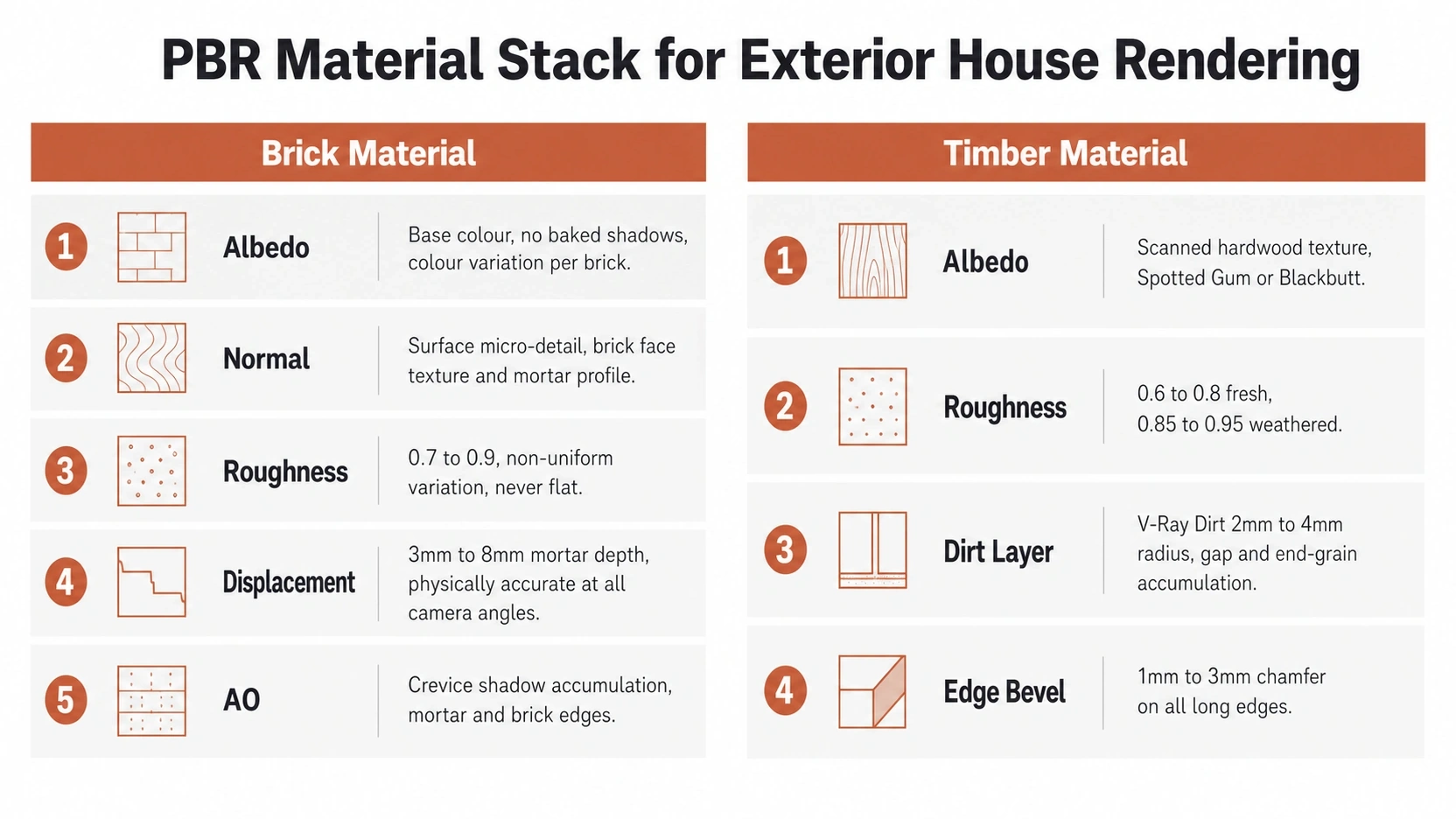
Five maps are the minimum for a production-quality brick material:
- Albedo: Base colour with no baked shadows or highlights. Add slight colour variation across individual bricks using a colour randomization map or multi-texture blend. Flat uniform albedo reads as manufactured.
- Normal: Surface micro-detail of the brick face and mortar profile. Handles fine texture that the displacement map does not resolve.
- Roughness: Values of 0.7 to 0.9 with non-uniform variation. A flat roughness value of 0.8 on every brick reads as plastic. The variation is what makes it read as stone.
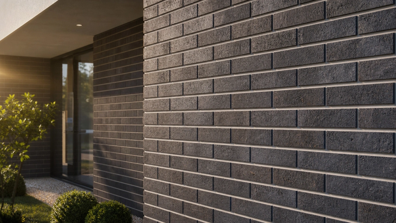
- Displacement: The critical map. Mortar joint depth in real brick ranges from 8mm to 12mm recessed. In V-Ray, set displacement amount to 3mm to 8mm. This physically offsets geometry so shadows fall correctly inside the mortar channel at every camera angle.
- Ambient Occlusion: Adds soft shadow accumulation in mortar channels and at brick edges. Without it, mortar lines look backlit rather than recessed.
Pre-calibrated PBR scans from Poly Haven (free) or Poliigon include all five channels mapped to real-world scale. These are already calibrated for physical accuracy and save significant setup time versus building from scratch.
Displacement vs Bump: When Each One Applies
Displacement maps physically offset the mesh. The mortar channel becomes actual geometry, and shadows inside it are driven by scene lighting from all angles. A bump map does none of this. It shifts surface normals to approximate depth, but the underlying geometry is flat, so the illusion fails the moment the camera is not perpendicular to the wall.
The production rule: displacement for any wall within 6 metres of the camera, bump for background walls beyond 15 metres where render budget matters and the camera angle is distant. For the hero facade in an exterior house rendering, displacement is correct. For the neighbour’s side wall at the edge of frame, bump is fine.
Apply displacement only to faces in the primary camera view. In 3ds Max, a separate material ID for hero versus background walls keeps control of which faces receive the heavy map and prevents unnecessary render-time overhead.
Getting Timber Cladding Right
Timber Scale and Shadow Lines
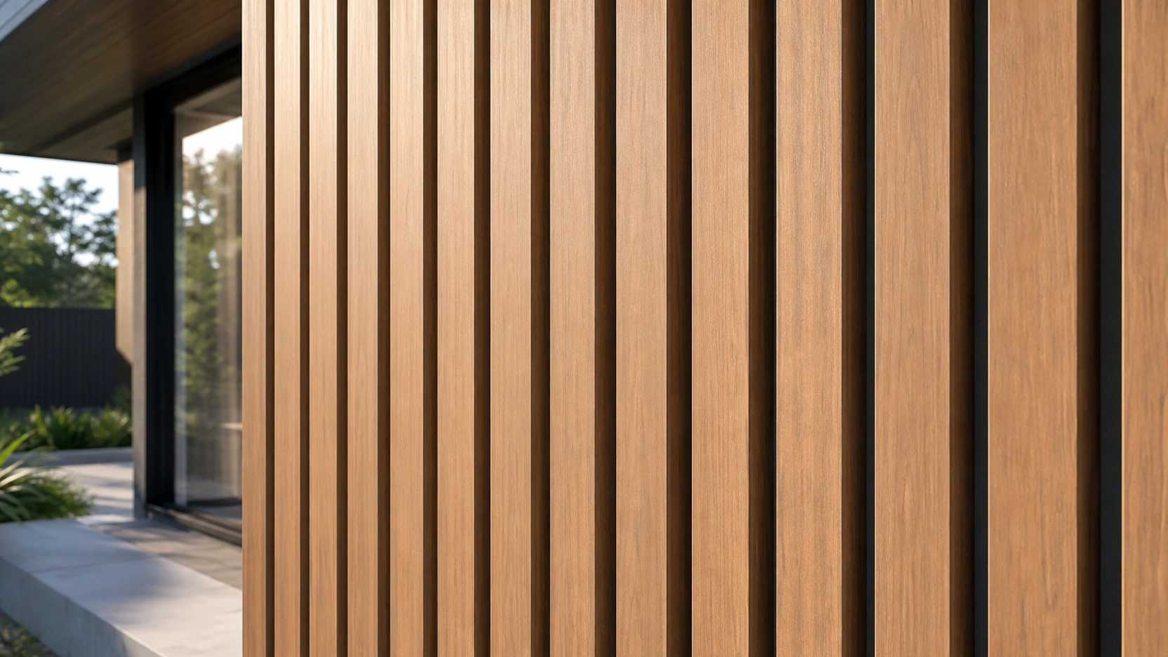
Vertical timber battens on a modern residential facade run at face widths of 90mm to 140mm with gaps of 15mm to 20mm between battens. These are construction dimensions, and they define the rhythm of shadow lines that makes timber cladding legible at camera distance.
At golden hour lighting (sun elevation 25 to 35 degrees), shadow from the leading edge of each batten falls across the gap and onto the face of the adjacent batten. This directional line of shadow is the primary visual texture of timber cladding at any camera distance. It only works when the gap between battens has physical depth in the geometry.
Model timber battens as individual mesh objects, not as a single flat plane with a timber texture applied. Each batten gets its own UV, its own slight roughness variation, and 1mm to 3mm beveled edges on all long edges. Real machined timber planks have chamfered or rounded arrises from the saw and planing process. Perfectly sharp 90-degree edges on CG timber identify it as digital.
For more on populating exterior scenes and placing entourage around residential homes, see our post on exterior 3D visualization people placement.
Timber Material Settings in V-Ray
Roughness values: 0.6 to 0.8 for fresh, unsealed hardwood (Spotted Gum, Blackbutt). Weathered or grey-wash finish: 0.85 to 0.95. Oiled or polished surface: 0.35 to 0.5 with slight anisotropy enabled in the grain direction.
Weathering detail is the step most renders skip. In V-Ray, layer a Dirt texture over the base albedo. Set the radius to 2 to 4mm. This accumulates occlusion colour (typically dark grey or near-black) in the recessed gaps between battens and at end-grain edges. A facade with correctly applied dirt accumulation reads as a building that has been rained on twice. Without it, the timber reads as just delivered from the supplier.
Lighting Sequence for Exterior House Rendering
Lighting sequence is where most exterior house rendering workflows go wrong. Material adjustments made against the wrong lighting produce wrong materials. The correct sequence:
- Place the HDRI first. Use a 16-bit EXR at 4K resolution minimum. Set exposure until the building silhouette reads correctly in a grey-box test render.
- Add V-Ray Sun if directional light is needed. Sun elevation of 25 to 40 degrees for morning or late afternoon. This angle creates shadows from brick course overhangs and from batten edges, giving both materials their texture depth. Sun above 60 degrees (noon) flattens everything.
- Lock the lighting. Do not change exposure or sun position after this step.
- Open the material editor. Adjust roughness first, then displacement scale. Run an IPR render at 50% resolution before committing to full output.
The golden hour rule for brick: at sun elevation below 30 degrees, individual brick faces cast shadows across adjacent mortar joints, making course lines read at full rendering distance. This is the lighting condition where brick-and-timber facades are most photorealistic, and the reason most professional exterior house rendering portfolios favour this time of day.
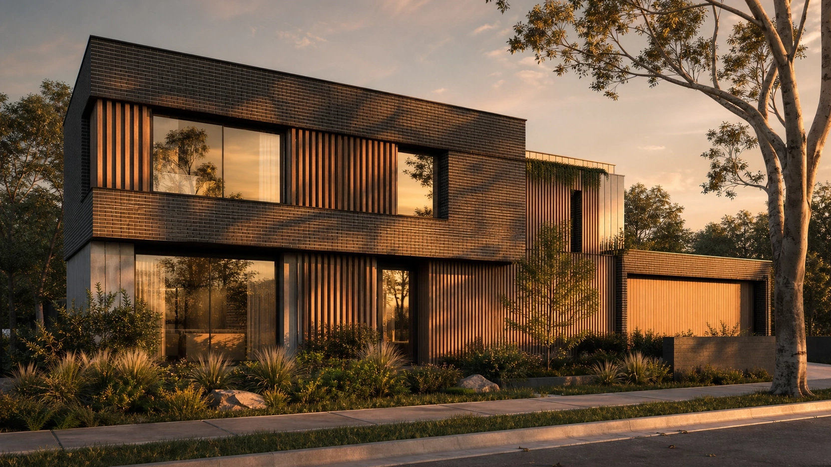
At our 3D Visualization Studio, lighting setup and displacement settings are specified in the project brief before any geometry is textured. The brief includes sun elevation, HDRI reference, and target texture scale. Changing these after texturing resets hours of material work.
What to Know
- Brick courses are 75mm (65mm face plus 10mm mortar). Use Real World Map Size in the UVW modifier, and add a UV randomizer for facades wider than 3 metres. Wrong scale is visible before any other material error.
- Five PBR maps for brick: Albedo, Normal, Roughness, Displacement, AO. Displacement is not optional for walls within 6 metres of the camera. Bump maps fail at oblique camera angles.
- Model timber battens as individual geometry with 1mm to 3mm beveled edges and 15mm to 20mm physical gaps. The shadow line between battens is the main visual event and requires geometry depth to render correctly.
- Layer V-Ray Dirt over timber albedo at 2 to 4mm radius. This step separates photorealistic timber from CG timber more than any other single setting.
- Establish lighting before adjusting materials. Lock sun elevation at 25 to 40 degrees before opening the material editor. Noon light eliminates brick texture depth.
Frequently Asked Questions
What is the correct brick scale for exterior house rendering?
Standard UK metric brick face is 65mm high and 215mm long. With a 10mm mortar joint, one brick course is 75mm tall. In 3ds Max, use the UVW Map modifier with Real World Map Size enabled and tile dimensions that match the source texture. A 3-metre wall should show 40 courses of brick. That proportion check confirms the UV scale before any render runs.
Should I use displacement or bump maps for brick in exterior rendering?
Displacement for walls within 6 metres of the camera. Displacement physically offsets geometry so mortar joint shadows are accurate at all camera angles. Bump maps are 2D normal illusions that flatten at oblique angles, which is where the camera is most commonly positioned for residential exteriors. For background walls beyond 15 metres, bump maps save render time without visible quality loss.
How do I stop brick texture from tiling visibly on a large facade?
Use a UV randomizer node or blend two to three brick textures with randomized UV rotation and offset per brick face. In 3ds Max with V-Ray, the Multi-Texture map node handles this. In Blender, use a texture coordinate node with a hash-based offset per face. Without randomization, any facade wider than 3 metres shows visible repeating patches.
What material settings should I use for timber cladding in V-Ray?
Roughness 0.6 to 0.8 for fresh hardwood, 0.85 to 0.95 for weathered or grey-wash finish. Layer a V-Ray Dirt texture over the base albedo at 2 to 4mm radius for grime accumulation in gaps and end-grain. Model battens as individual geometry with 1mm to 3mm beveled edges. Without the bevel and dirt, the timber reads as manufactured rather than installed.
What lighting angle works best for exterior house rendering with brick?
Sun elevation 25 to 40 degrees, representing morning or late afternoon. At this angle, individual brick faces cast shadows across adjacent mortar joints, making course lines read at full rendering distance. Sun above 60 degrees produces flat light that eliminates texture depth. Golden hour (10 to 20 degrees) maximises drama but risks over-warm colour grading that shifts brick tones into orange territory.
Conclusion
Brick-and-timber facades are the defining material palette of contemporary residential architecture in most markets. Getting them to read as photorealistic in an exterior house rendering is a technical decision made at the project setup stage, not a post-production correction.
In our studio, texture scale, displacement settings, and lighting elevation are written into the project brief before any geometry is textured. That sequence is what produces an exterior render that reads as a photograph rather than a visualisation. If you are working on a residential exterior project and want that standard of output, visit our exterior rendering services page or send us your project details for a quote here .