

3D Floor Plan: The Information Problem Behind the Translation
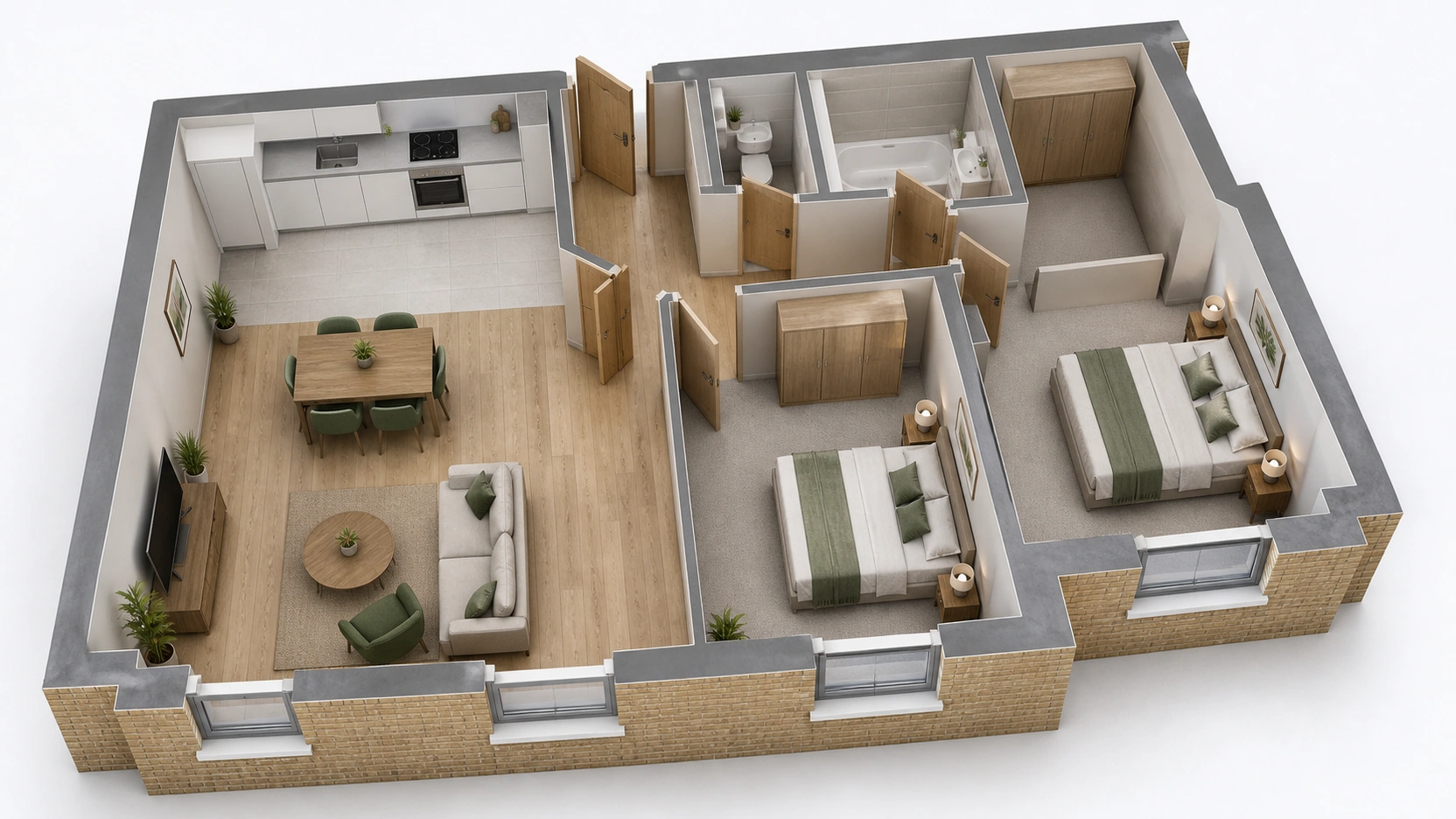
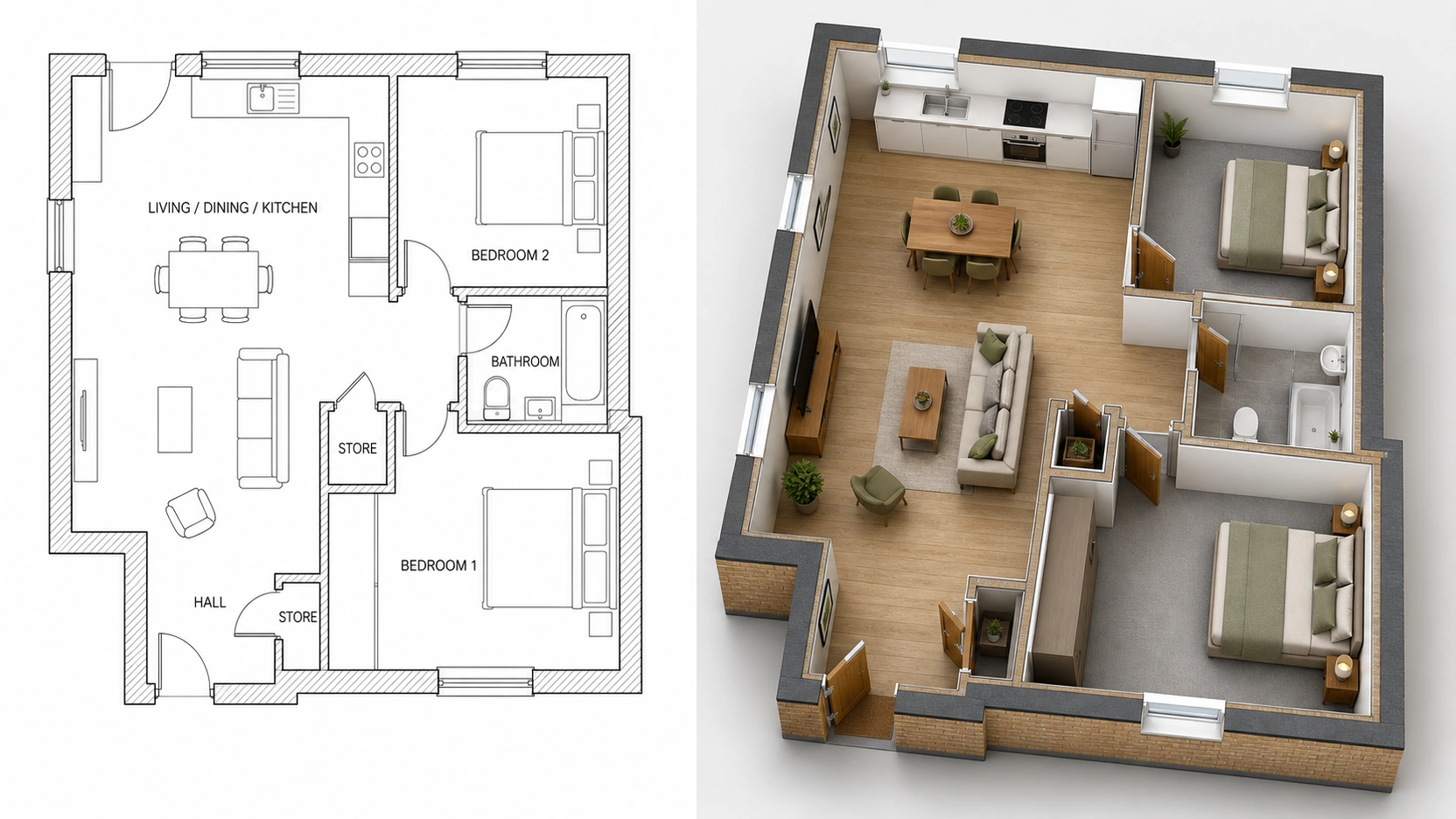
What a 2D CAD Floor Plan Contains, and What It Does Not
A standard architectural 2D floor plan at planning or pre-application design stage is drawn to communicate horizontal layout. What it reliably contains:
- Room footprints with internal dimensions
- Wall positions (typically drawn to structural wall face, without finish layers)
- Door positions and swing direction
- Window positions (shown as a gap in the wall line with a frame indicator)
- Staircase positions (shown as hatched or numbered treads)
- Structural columns (shown as filled squares or circles)
- Room name annotations and floor area labels
What a standard 2D CAD floor plan does not contain, and which the studio must infer, measure from other drawings, or assume before modelling can begin:
- Floor-to-ceiling height: The vertical extent of the space. Found on a section drawing or room schedule, not on a plan view.
- Window sill height: Typically 900mm in UK residential, 1100mm in commercial, but varies by specification.
- Window head height: The height at which glazing ends. Determines how much solid wall sits above the window frame.
- Door head height: Standard UK residential internal doors: 2040mm. High-specification residential and commercial: 2100mm.
- Wall thickness including finishes: CAD walls are often drawn as simplified lines representing structural positions, not finished construction thicknesses. A 100mm blockwork internal wall has 100mm structural + 12.5mm plasterboard + 3mm skim on each side = 131mm finished.
- Mezzanine, terrace, and balcony levels: Elements that exist at non-standard heights and require section or elevation drawings to resolve.
Every one of these missing dimensions is a decision point in the 3D floor plan production process. Decisions made correctly produce a 3D floor plan that reads as an accurate representation of the proposed space.
The Vertical Dimension: A Six-Level Inference Hierarchy
When a 3D floor plan studio receives a 2D plan without section drawings, elevations, or a room data schedule, all vertical dimensions are inferred from a priority hierarchy.
- Explicit annotations on the plan itself. Some architects note non-standard ceiling heights in room name labels (e.g., “Living/Dining 2.7m CH”) or in a general arrangement note. If a dimension is explicitly annotated on the supplied drawing, it supersedes all other assumptions.
- Section and elevation drawings if provided. Section drawings show the full vertical profile of the building. Elevation drawings show external facade heights. These are the most reliable sources of vertical information when the plan lacks annotations.
- Planning consent documents. For UK projects with planning permission, the Design and Access Statement and planning drawings submitted to the LPA are publicly available and often contain floor-by-floor ceiling height specifications. These can be retrieved from the LPA’s planning portal for any approved scheme.
- Building Regulations minima. The UK Building Regulations Approved Document F (England) specifies a minimum ceiling height of 2.3m for habitable rooms. If the project complies with Building Regulations and no higher specification is indicated, 2.3m is the minimum credible assumption.
- UK residential construction standards. In the absence of explicit specification, standard new-build residential ceiling heights in the UK are: 2.4m finished on the ground floor, 2.35m on upper floors. This reflects typical structural slab and timber joist construction depths. Premium residential: 2.7-3.0m. Commercial offices: 2.7-3.6m underside of ceiling tile.
- Documented default assumptions, confirmed with the client. If no information is available from levels 1-5, the studio applies standard residential defaults (2.4m ground floor, 2.35m upper floors), documents these assumptions in the brief confirmation, and asks the client to confirm before modelling proceeds.
Modelling to incorrect ceiling heights affects every aspect of the 3D floor plan, window proportions, door scale, furniture-to-ceiling relationship, and the overall spatial impression of the space.
The DWG Layer Problem: Why File Hygiene Determines Cost
A CAD file has a layer structure. The quality of that structure is the single largest variable in 3D floor plan production cost, more impactful than the size or complexity of the plan.
A well-structured DWG follows a naming convention. For UK architectural practices, this is typically ACA or the UK-native NBS/Uniclass layer naming convention. Layer names in a well-structured DWG include:
A-WALL-INT, internal wallsA-WALL-EXT, external wallsA-DOOR, door leaves and framesA-GLAZ, glazing elementsA-ANNO, annotations, dimensions, and textA-FURN, furniture
When a DWG is structured this way, the modeller can isolate and freeze irrelevant layers, leaving a clean geometric underlay showing only wall and opening geometry for direct tracing.
A poorly structured DWG puts everything on layer 0, or spreads walls, dimensions, annotations, hatches, and furniture across unsystematic layer names. The practical consequence: a clean, well-layered DWG for a standard 2-bedroom flat (55-65 sqm) can be prepped and used as an underlay in 1-2 hours. A poorly structured DWG of the same flat requires manually identifying and deleting or moving text, dimension lines, annotation blocks, overlapping polylines, and non-closed wall geometry, adding 2-6 hours of cleaning time before modelling begins.
For a studio offering a fixed-price 3D floor plan service, this difference is built into the two-tier pricing common across the industry: “clean DWG” and “PDF only / unstructured file” rates, with the latter attracting a supplementary fee of approximately £50-150 to cover additional cleaning time.
What a 3D Floor Plan Is, and What It Is Not
The term “3D floor plan” is used inconsistently across property marketing and architectural visualization. For clarity:
A 3D floor plan is a specific rendered image type showing the floor plan of a property from an oblique aerial camera position, typically 45-60 degrees above the plan, with the walls extruded to the appropriate ceiling height, furnished at correct scale, and rendered with materials, lighting, and shadows. Standard UK property marketing specifications:
- Output resolution: 4500x3000px at 300dpi (A3 print-ready)
- Camera angle: 45-60 degree oblique, orthographic or mild perspective projection
- Wall height: rendered to finished ceiling height
- Furniture: staged at correct scale for the room configuration
- Materials: simplified but representative, timber flooring, carpet, tile, without full photorealistic complexity
- Lighting: flat overhead or soft ambient, sufficient to read the spatial layout clearly
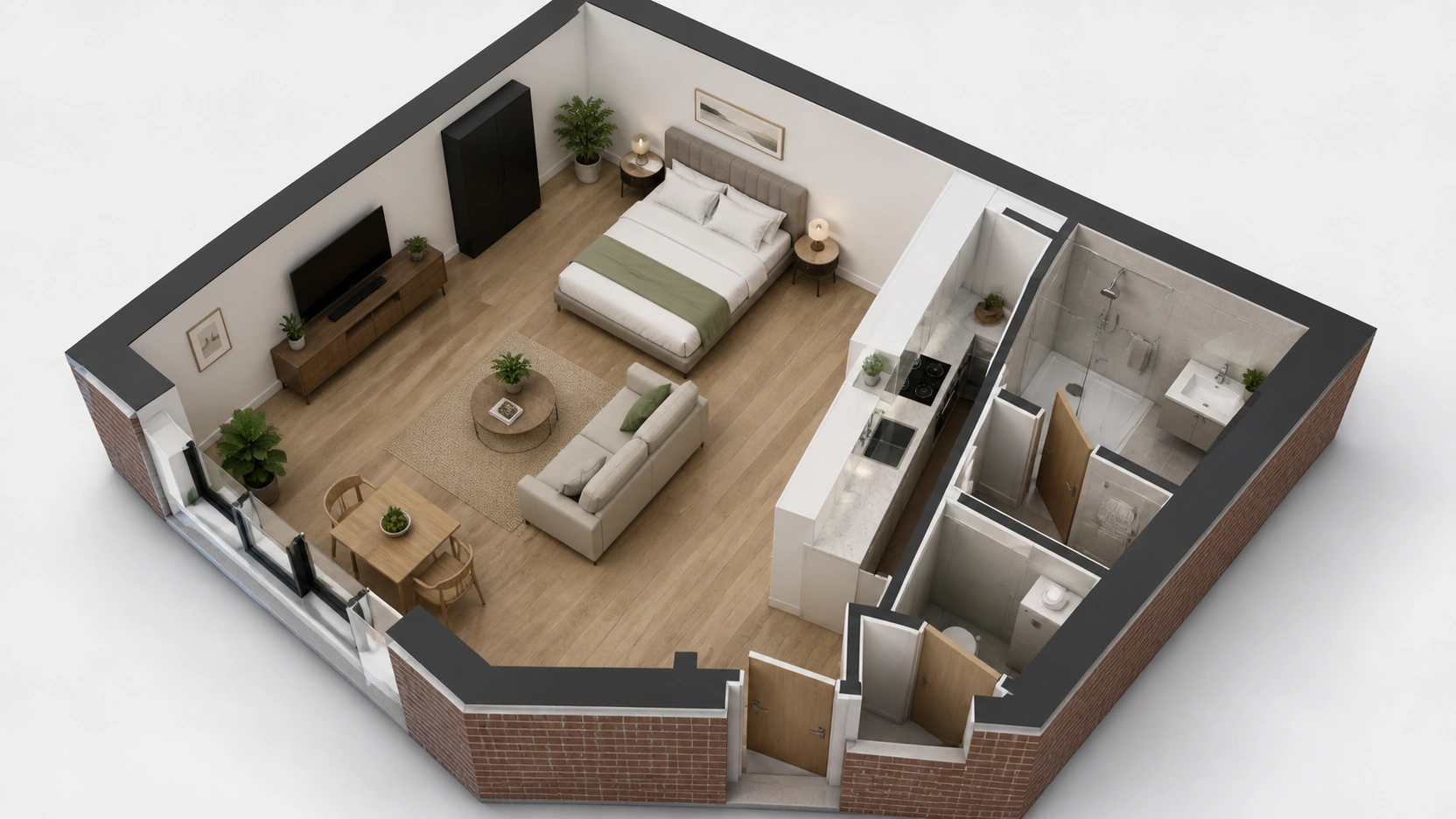
What a 3D floor plan is not:
- Not an interior rendering: Interior rendering is a photorealistic image from an eye-level camera position inside a specific room. A 3D floor plan is a plan-view oblique image. Different products, different purposes, different production costs.
- Not a walkthrough or animation: A 3D floor plan is a single static rendered image.
- Not an interactive plan: Interactive clickable plans are a separate product using the 3D floor plan as a reference but requiring additional web development work.
Confirming which specific product is required before briefing a studio prevents the most expensive category of revision.
UK Wall Thickness Standards for 3D Floor Plan Accuracy
In the 3D model underlying a 3D floor plan render, wall thicknesses determine room proportions. If all walls are modelled at a uniform 100mm, the finished rooms are slightly wider than they would be in the real building.
| Wall Type | Construction | Finished Thickness |
|---|---|---|
| External cavity wall | 102mm brick + 75mm cavity + 100mm block + 12.5mm board + 3mm skim | 292-330mm (modelled at 300mm) |
| Internal loadbearing (blockwork) | 100mm block + 12.5mm board + 3mm skim (×2 sides) | 131mm (modelled at 130mm) |
| Internal non-loadbearing (stud) | 100mm stud + 12.5mm board + 3mm skim (×2 sides) | 131mm (modelled at 130mm) |
| Party wall (between dwellings) | 215mm block + acoustic board + finishes | 240-250mm (modelled at 250mm) |
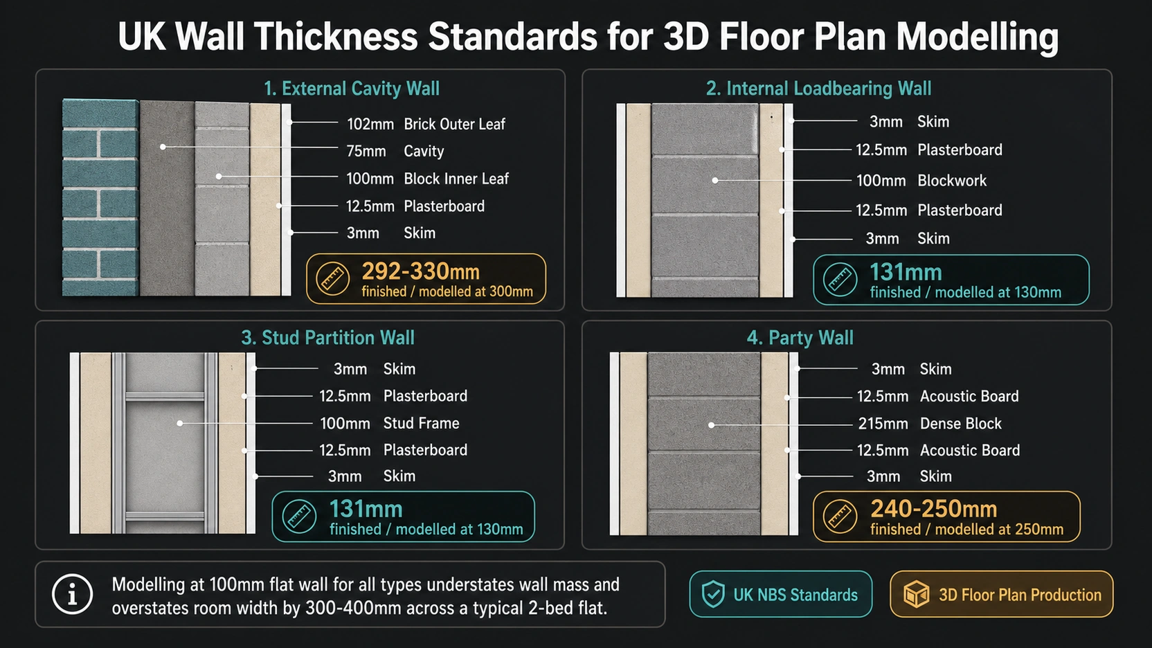
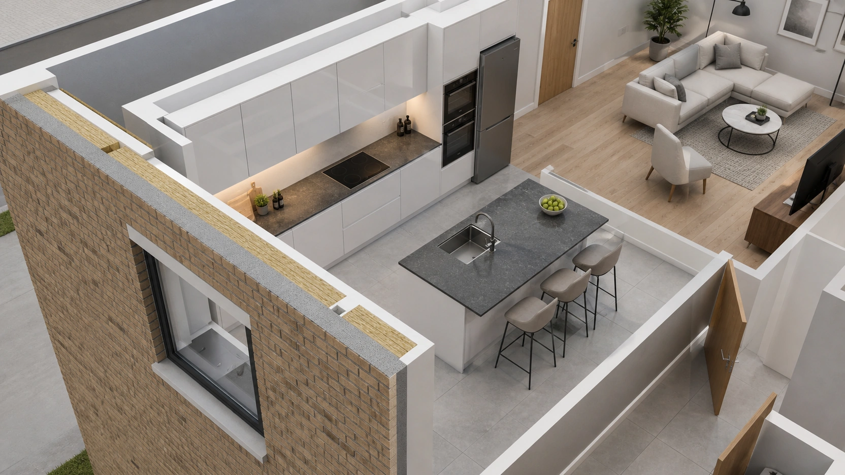
The consequence of under-modelling wall thickness: a 3D floor plan of a 2-bedroom flat with 10 internal wall segments, each modelled at 100mm instead of 130mm, will show rooms that appear approximately 300-400mm wider in total than the real rooms, a discrepancy that becomes visible when buyers test furniture placement against the plan.
At Our Archviz Studio, 3D floor plan projects begin with a file review before quoting, confirming the DWG layer structure, identifying which vertical dimensions are explicitly documented and which require assumptions, and specifying whether the output is a marketing 3D floor plan or a design document. These decisions are confirmed before production begins.
Quick Reference
- A 2D CAD floor plan is a horizontal document. It contains room footprints, wall positions, door swings, and window gaps, but contains no floor-to-ceiling height, window sill or head height, door head height, or finished wall thickness. Every 3D floor plan requires the studio to reconstruct these vertical dimensions before modelling begins.
- Vertical dimensions are inferred from a six-level priority hierarchy: explicit annotations on the plan, section and elevation drawings, planning consent documents (LPA planning portal), Building Regulations minima (2.3m for habitable rooms, Approved Document F), UK residential construction standards (2.4m ground floor, 2.35m upper floors), and documented default assumptions confirmed with the client before modelling.
- DWG layer hygiene is the single largest variable in 3D floor plan production cost. A well-structured DWG with NBS/Uniclass layer naming (A-WALL-INT, A-WALL-EXT, A-DOOR, A-GLAZ, A-ANNO) reduces model preparation time by 2-6 hours versus an unstructured DWG, the reason most studios charge a £50-150 supplementary fee for PDF-only or unstructured file submissions.
- A 3D floor plan is a specific rendered image product: an oblique aerial view (45-60 degrees) of a furnished, material-correct floor plan rendered to 4500x3000px at 300dpi for A3 property marketing. It is not an interior rendering (eye-level photorealistic still), not a walkthrough, and not an interactive plan. UK wall thickness standards: external cavity 300mm, internal blockwork and stud 130mm, party wall 250mm, uniform 100mm modelling overstates room width by 300-400mm across a typical 2-bedroom flat.
Frequently Asked Questions
What is a 3D floor plan?
A 3D floor plan is a rendered image showing a property’s floor layout from an oblique aerial camera position, typically 45-60 degrees above the plan. Walls are extruded to the correct ceiling height, rooms are furnished at scale, and materials are applied to indicate floor type, wall finish, and ceiling. The result replaces the traditional 2D black-and-white architectural floor plan with a spatially legible, furnished image that a non-technical buyer can read immediately. Standard UK property marketing output: 4500x3000px at 300dpi for A3 print. A 3D floor plan is a static rendered image, not an interactive plan, a walkthrough, or an interior rendering.
What CAD files does a studio need to produce a 3D floor plan?
A DWG (AutoCAD format) floor plan is the preferred input. It provides the horizontal geometry, wall positions, door and window openings, room footprints, as vector geometry that can be imported directly into the modelling software as a precision underlay. A PDF or scanned plan is also workable but adds cleaning and tracing time, typically reflected in a supplementary fee of £50-150. The DWG should be structured with walls, doors, glazing, and annotations on separate named layers, a well-structured DWG reduces production time by 2-6 hours versus an unstructured file. The studio will also need confirmation of ceiling heights, window sill and head heights, and door heights, either from section drawings or from the client’s specification.
What ceiling height is assumed for a 3D floor plan if no drawings specify it?
When no ceiling height is explicitly documented, studios apply UK residential construction standards: 2.4m finished ceiling height on the ground floor, 2.35m on upper floors. These values reflect typical UK slab and joist construction depths for standard new-build residential. For premium residential, 2.7-3.0m is used. For commercial, 2.7-3.6m depending on specification. The UK Building Regulations Approved Document F (England) specifies a minimum of 2.3m for habitable rooms. Any assumptions are documented and confirmed with the client before modelling begins, incorrect ceiling heights affect window proportions, door scale, and the spatial impression of the 3D floor plan.
How long does it take to produce a 3D floor plan?
For a standard 2-bedroom residential flat (55-65 sqm): 1-2 working days from clean DWG receipt to final render, or 2-3 working days from an unstructured or PDF-only submission. The primary variables affecting production time are: DWG layer hygiene (a clean, well-layered file with NBS/Uniclass layer names reduces preparation time significantly), completeness of vertical dimension data (missing ceiling heights or window details require confirmed assumptions before proceeding), and the number of rooms and their complexity. Multi-floor projects are quoted per floor.
What is the difference between a 3D floor plan and an interior rendering?
A 3D floor plan is an oblique aerial view of the entire floor layout from above, showing room proportions, furniture layout, and spatial relationships between rooms at a 45-60 degree camera angle. An interior rendering is a photorealistic image from an eye-level camera position inside a specific room, showing materials, lighting, atmosphere, and finish quality in detail. Both use the same underlying 3D model but serve different purposes. A 3D floor plan communicates spatial layout for property marketing and buyer decision-making. An interior rendering communicates design quality and material choices for aspirational marketing content. Most development marketing packs include both.
Conclusion
A 3D floor plan is a translation product. Its quality depends on the completeness of the 2D information provided, the accuracy of the vertical dimension assumptions made, the structure of the DWG file received, and the correct application of UK construction standards to wall thickness and room height. Understanding the information problem behind the translation, not just the software workflow, is what determines whether the finished 3D floor plan reads as a spatially accurate representation of a real space or as an approximate impression of it.
At RenderInfinity, 3D floor plan projects begin with a file review and brief confirmation before production. Visit our 3D floor plan services page to submit your drawings and receive a quote.